Demand for new‑build and expansion projects of environmental‑monitoring laboratories has risen remarkably in recent years. Carbon emission verification and testing driven by carbon‑neutrality initiatives, mandatory in‑house monitoring requirements under pollutant discharge permit regulations, and capacity‑building programs for local environmental‑monitoring stations have all contributed to this trend. Nevertheless, constructing a qualified environmental‑monitoring laboratory is a complex undertaking. It covers testing for multiple media including water, air, noise and solid waste. Different testing categories impose divergent requirements for zoning, ventilation and cleanliness. Inadequate planning will almost inevitably lead to costly later‑stage modifications. This article outlines six critical decision‑making points to support thorough planning during the design phase.
Site Selection: Environmental‑Monitoring Laboratories Cannot Be Set Up Arbitrarily
Special site‑selection criteria apply to environmental‑monitoring laboratories, and simple rental of ordinary office space is not sufficient. First, the surrounding area must be free of strong pollution sources. If the laboratory is located close to heavy‑traffic roads or industrial emission sources, background values for atmospheric sampling will be elevated, directly compromising the representativeness and accuracy of test results. Third‑party laboratory accreditation assessments pay close attention to background environmental quality at the laboratory location.
Second, floor load capacity must meet requirements. Zones housing large precision instruments such as ICP‑MS shall feature a minimum live‑load rating of 4.0 kN/m² (approximately 400 kg per square metre). Actual values shall be calculated according to equipment weight, layout and operational requirements. Load calculations are also required for gas cylinder storage rooms with multiple rows of compressed‑gas cylinders. This represents a common pitfall for laboratories housed within rented office buildings, where typical office floor live‑load ratings are generally only 2.0 kN/m² (approximately 200 kg per square metre).
Third, drainage and exhaust conditions must be satisfied. Large volumes of acidic waste liquid are generated in pre‑treatment zones, requiring reserved space for neutralisation processes. Outdoor exhaust outlets shall not be positioned directly facing fresh‑air intakes of the building, and discharge heights shall comply with local environmental assessment specifications.
Zoning and Layout: Physical Separation Is Mandatory for Organic and Inorganic Analysis Areas
One non‑negotiable principle for functional zoning of environmental‑monitoring laboratories is that organic‑analysis zones and inorganic‑analysis zones must be fully independent in both spatial arrangement and air‑handling systems. Solvent vapours such as n‑hexane and dichloromethane from organic‑analysis operations that drift into inorganic‑analysis zones will cause severe carbon‑based interference during trace heavy‑metal testing with ICP‑MS. Detection limits for elements including arsenic and selenium may increase by several‑fold or even tens‑of‑fold, resulting in detection failures for low‑concentration samples.
Practical implementation includes separating organic‑analysis and inorganic‑analysis zones with solid partition walls, with aisles or buffer rooms in‑between. Shared air‑return ducts are prohibited. Supply and exhaust air systems for the two zones shall operate completely independently to eliminate cross‑airflow.
In addition, pre‑treatment zones and instrument rooms must also be separated. Acid vapours generated during digestion procedures, including nitric acid, hydrochloric acid and hydrofluoric acid, are highly corrosive to optical components and circuit boards of precision instruments. Pre‑treatment zones shall be enclosed as independent spaces with solid walls.
Ventilation System: Distinct Ventilation Requirements for Three Types of Zones
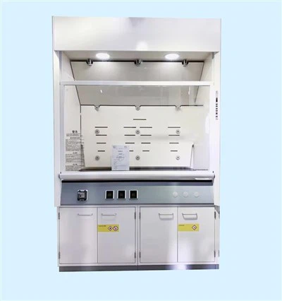
Ventilation design for environmental‑monitoring laboratories shall be implemented on a zone‑by‑zone basis. Pre‑treatment zones impose the highest ventilation load. For a standard 1.5‑metre fume hood with a face velocity of 0.5 m/s, exhaust air volume ranges from 1500 m³/h to 2000 m³/h per unit. A typical pre‑treatment zone requires two to three fume hoods, plus general room‑air exchange of no less than six air changes per hour. Adequate make‑up air is essential. Large‑volume exhaust must be matched with equivalent fresh‑air supply; otherwise excessive negative pressure will occur inside the laboratory, hindering door operation and destabilising air‑conditioning temperature control.
Ventilation for calibration‑gas storage rooms is frequently overlooked. Common calibration gases for environmental monitoring such as CO, SO₂, NO and NO₂ are mostly heavier than air and tend to accumulate close to ground level upon leakage. Exhaust outlets shall be installed at low height, no higher than 300 mm above floor level, with no fewer than 12 air changes per hour. Flammable gases and oxidising gases shall be stored separately, and gas‑leakage alarm devices shall be fitted.
Microbiology zones adopt an independent ventilation system. A three‑stage filtered air‑supply solution using primary‑efficiency, medium‑efficiency and high‑efficiency filters shall be applied to maintain positive‑pressure conditions, with 10‑15 air changes per hour. Its air‑handling system shall be fully isolated from chemical‑processing zones.
Workbenches and Cabinetry: Material Selection Tailored to Different Zones
Uniform material selection across the whole laboratory is not advisable. Pre‑treatment zones and physicochemical‑analysis zones require all‑steel‑frame workbenches with acid‑and‑alkali‑resistant physicochemical countertops. Ordinary steel‑wood workbenches will suffer rapid moisture‑induced deformation of wooden cabinet components and frame corrosion under acid‑vapour exposure.
Instrument‑analysis zones need vibration‑isolated instrument benches. Precision instruments such as ICP‑MS and GC‑MS are highly vibration‑sensitive. Instrument benches shall adopt independent concrete foundations or steel anti‑vibration supports and shall not share supporting structures with walls or other laboratory furniture.
Microbiology zones shall use stainless‑steel countertops for convenient disinfection with alcohol or steam. Ultraviolet sterilisation lamps shall be installed at each workstation. Calibration‑gas storage rooms do not require fixed workbenches; stainless‑steel gas‑cylinder racks with anti‑tipping chains are sufficient.
Waste‑Gas and Waste‑Liquid Treatment: Planning Cannot Be Deferred Until Late‑Stage Construction
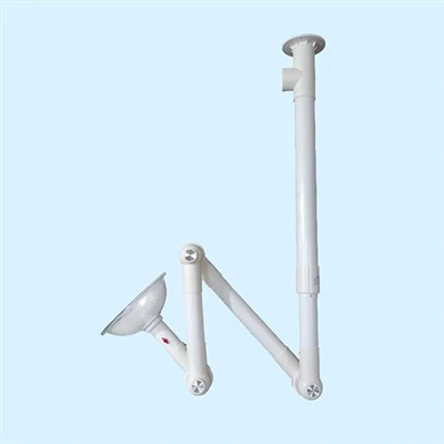
Postponing waste‑treatment planning until shortly before laboratory accreditation assessment will very likely result in non‑compliance. For waste gas: Acid mist generated during acid digestion shall be treated by waste‑gas processing equipment prior to discharge. Exhaust air from organic‑solvent handling shall pass through activated‑carbon adsorption units before release.
For waste liquid: Acidic heavy‑metal‑containing waste liquid, organic‑extraction waste liquid, cyanide‑containing waste liquid and other categories shall be collected separately, with each container clearly labelled with waste type and generation date. Flooring inside waste‑liquid temporary‑storage rooms shall be epoxy‑resin‑coated for anti‑seepage purposes, and surrounding containment bunds shall be installed. Complete records shall be maintained covering generation, temporary storage and outsourced disposal of each batch of waste liquid. These measures are key assessment items during both third‑party laboratory audits and routine inspections by environmental authorities.
Alignment With Laboratory Accreditation: Synchronise Design and Certification Preparation to Save Time
Full laboratory‑accreditation procedures normally take 6‑12 months. Time can be saved by integrating accreditation requirements into the design phase. Accreditation consultants may participate during drawing review, translating assessment criteria directly into floor‑plan layout and equipment selection. Examples include dedicated access routes reserved at the drawing stage, layout of continuous temperature‑and‑humidity monitoring points during electrical‑system design, and anti‑seepage flooring plus containment bunds for waste‑liquid storage rooms implemented during civil‑engineering construction. Remedial retrofits after completion of construction will incur high costs or lead to non‑compliance during assessment.
Practical experience from environmental‑monitoring‑lab projects demonstrates that the design phase offers the best opportunity to reduce overall expenditure with reasonable upfront investment. Ventilation‑system duct routing, physical separation of functional zones, and waste‑gas and waste‑liquid treatment schemes become difficult or impossible to modify once construction commences. All such elements must be finalised at the drawing‑design stage.